Design Flow Chart Of Vlsi
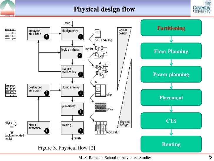
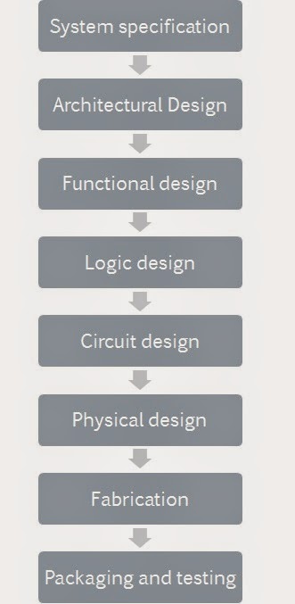
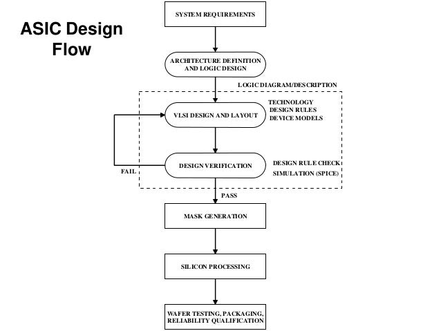
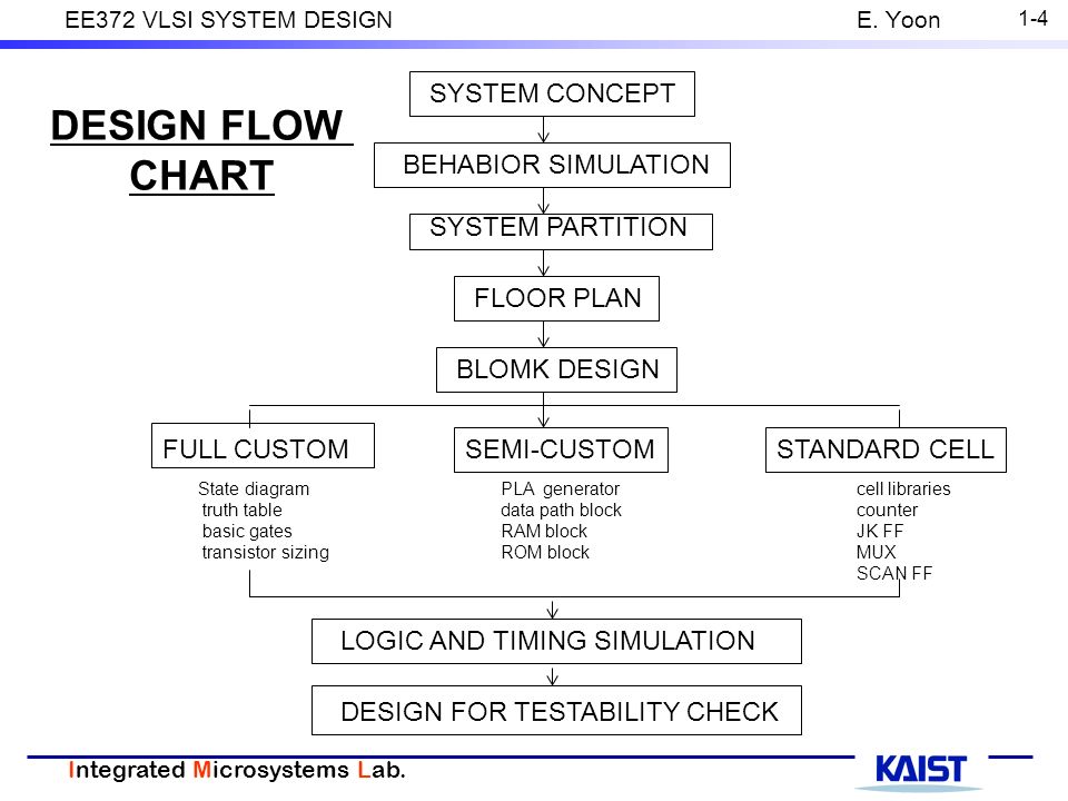
Vlsi design flow the vlsi design cycle starts with a formal specification of a vlsi chip follows a series of steps and eventually produces a packaged chip.
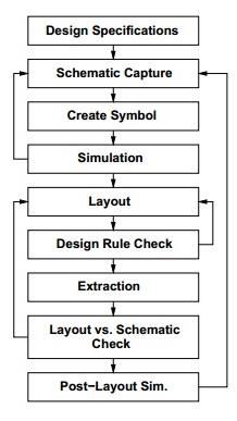
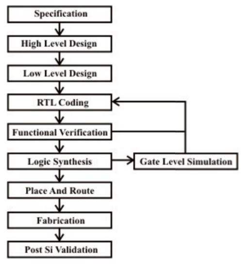
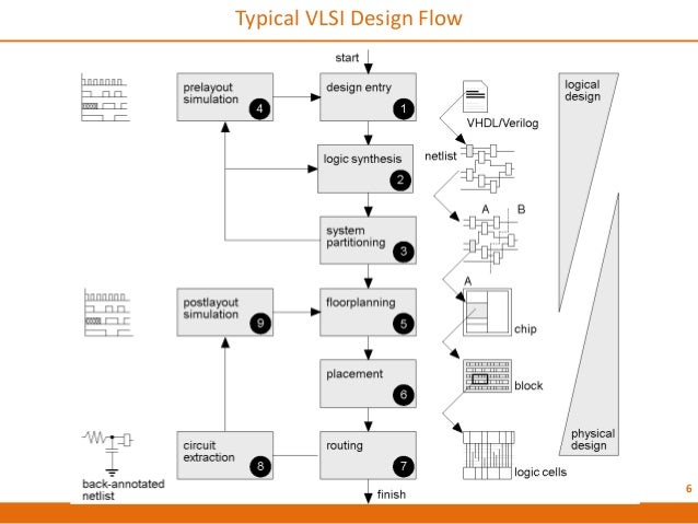
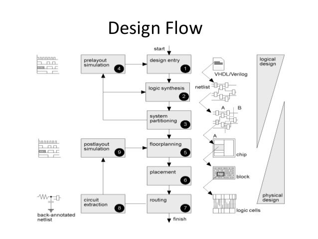
Design flow chart of vlsi. There are different types of design procedures for analog digital designs and. A typical design cycle may be represented by the flow chart shown in figure. The chip design includes different types of processing steps to finish the entire flow. A robust and silicon proven flow a good understanding of the chip specifications and constraints and an absolute domination over the required eda tools and their reports.
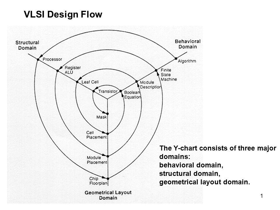
For anyone who just started his carrier as a vlsi engineer has to understand all the steps of the vlsi design flow to become good in his area of operations. 7 front end design logical design consists of following steps 1. In this video i will be explaining you all about the design flow and easy way to draw y chart and its three domains behavioral structural and geometrical layout related to vlsi design. To succeed in the vlsi design flow process one must have.
Design entry enter the design in to an asic design system using a hardware description language hdl or schematic entry 2. Logic synthesis generation of netlist logic cells and their connections from hdl code.
