Explain Vlsi Design Flow Using Y Chart

A typical design cycle may be represented by the flow chart shown in figure.
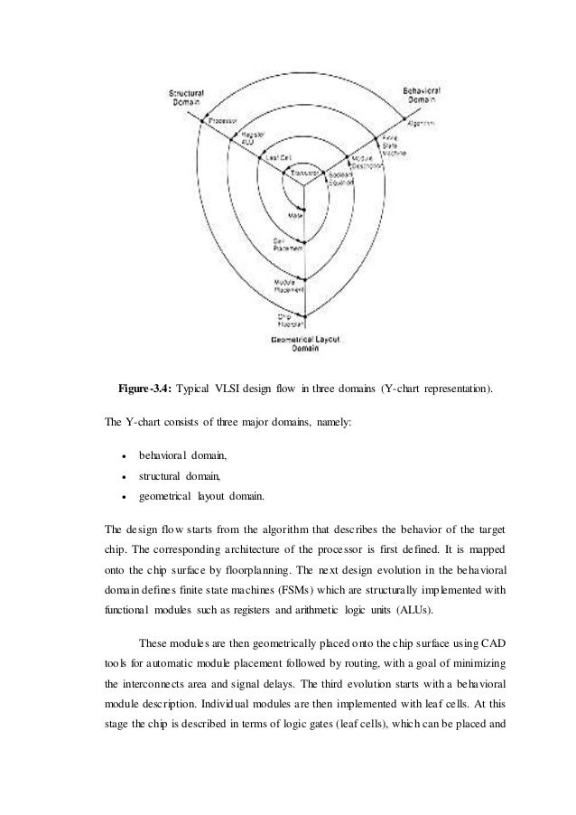
Explain vlsi design flow using y chart. The gajski kuhn chart or y diagram depicts the different perspectives in vlsi hardware design. According to this model the development of hardware is perceived within three domains that are depicted as three axis and produce a y. The various levels of design are numbered and the blocks show processes in the design flow. The three domains of the gajski kuhn y chart are on radial axes.
Vlsi design flow is not exactly a push button process. Academia edu is a platform for academics to share research papers. Daniel gajski and robert kuhn developed it in 1983. A robust and silicon proven flow a good understanding of the chip specifications and constraints and an absolute domination over the required eda tools and their reports.
Vlsi design styles part 1 duration. In this video i will be explaining you all about the design flow and easy way to draw y chart and its three domains behavioral structural and geometrical layout related to vlsi design. In 1985 robert walker and donald thomas refined it. Specifications comes first they describe abstractly the functionality interface and the architecture of the digital ic circuit to be designed.
Vlsi design 4 y chart the gajski kuhn y chart is a model which captures the considerations in designing semiconductor devices. Mostly it is used for the development of integrated circuits. Each of the domains can be divided into levels of abstraction using concentric rings. To succeed in the vlsi design flow process one must have.
The vlsi design cycle starts with a formal specification of a vlsi chip follows a series of steps and eventually produces a packaged chip. Along with this axis the abstraction levels that describe the degree of abstraction. Vlsi physical design 34 915 views. Mostly it is used for the development of integrated circuits.


