Flow Chart Of Vlsi Design Flow

There are different types of design procedures for analog digital designs and.
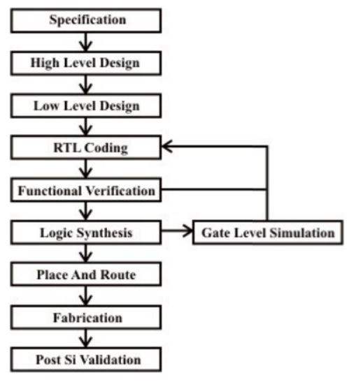
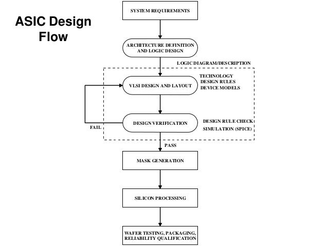
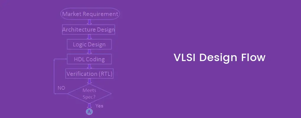
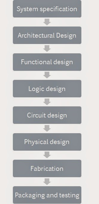
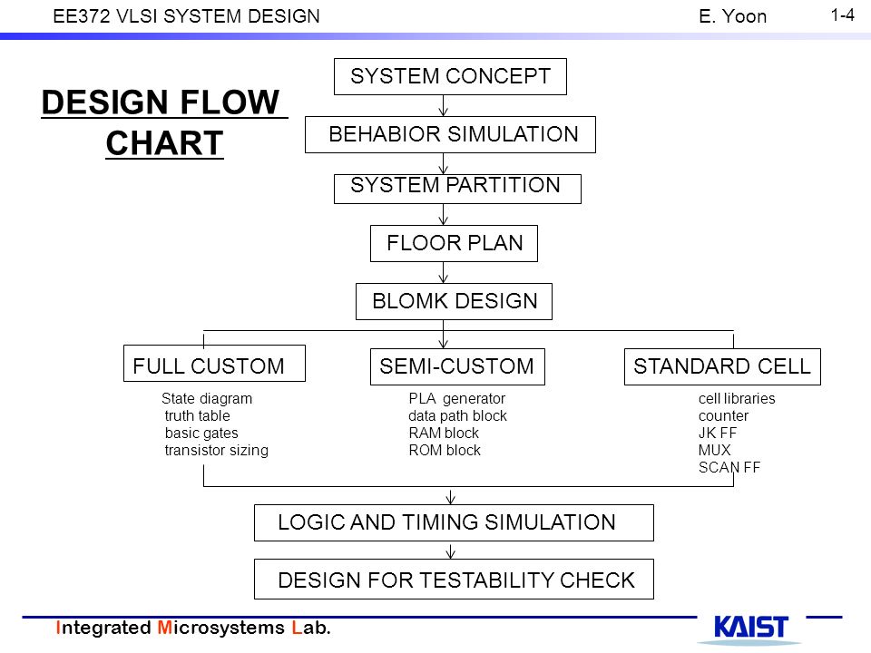
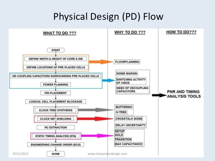
Flow chart of vlsi design flow. Specifications comes first they describe abstractly the functionality interface and the architecture of the digital ic circuit to be designed. The chip design includes different types of processing steps to finish the entire flow. The various levels of design are numbered and the blocks show processes in the design flow. And also for an fpga based digital design the flow is different from that of an asic.
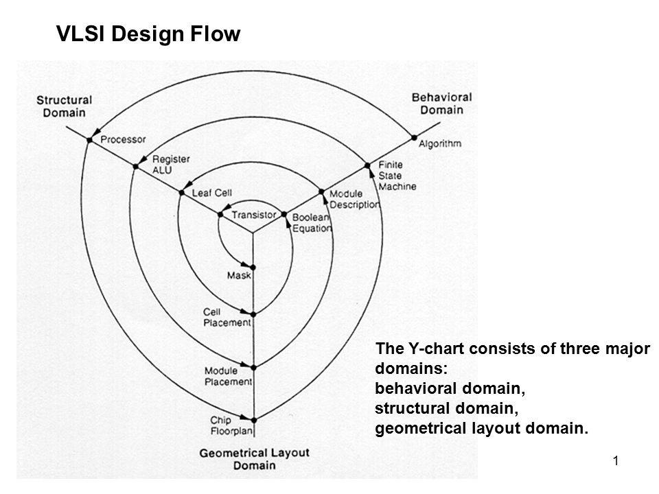
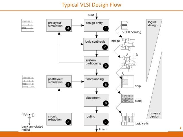
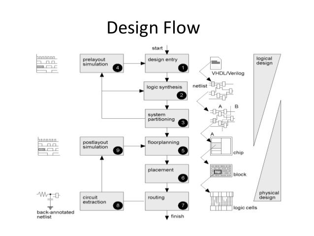
The various level of design are numbered and the gray coloured blocks show processes in the design flow. Vlsi design flow concept behavior specification designer manufacturing design final product validation product verification advanced reliable systems ares lab. Vlsi design flow the vlsi design cycle starts with a formal specification of a vlsi chip follows a series of steps and eventually produces a packaged chip. Specifications comes first they describe abstractly the functionality interface and the architecture of the digital ic circuit to be designed.
Jin fu li ee ncu 8 behavior synthesis rtl design logic synthesis netlist logic gates layout synthesis rtl layout masks verification layout verification logic verification. For each and every step the design process requires a dedicated eda tool. For anyone who just started his carrier as a vlsi engineer has to understand all the steps of the vlsi design flow to become good in his area of operations. The vlsi ic circuits design flow is shown in the figure below.
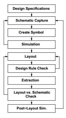
A design flow in vlsi is the sequence of processes steps involved in the making of an integrated circuit. A typical design cycle may be represented by the flow chart shown in figure. 7 front end design logical design consists of following steps 1. Academia edu is a platform for academics to share research papers.
Design entry enter the design in to an asic design system using a hardware description language hdl or schematic entry 2. Logic synthesis generation of netlist logic cells and their connections from hdl code. The vlsi ic circuits design flow is shown in the figure below. The picture below shows the various steps of the design flow.
6 typical vlsi design flow 7. A robust and silicon proven flow a good understanding of the chip specifications and constraints and an absolute domination over the required eda tools and their reports. These tools have the flexibility to import or export different types of files. Vlsi design flow is not exactly a push button process.
